A Home Brew Hand Pump
The problem
In the past I have bought hand pumps from various marine retail establishments. A couple were of good quality. Most though had problems. They would work ok when I first got them but after sitting in the locker for a few months I would find that they did not work well. The problem was that they failed to develop suction because the pump piston did not seal properly against the rubber. As one can imagine this is frustrating especially when it causes a delay or postponement of a boat project.
The one incident that sent me over the top was when I was attempting to fix the Volvo Penta diesel engine. I had bought a new hand pump at a well known marine retailer and paid good money for it thinking that it would do the job. This pump had a brass tube with red end caps. When I opened the package and tried to pump oil and water mixture from the crank case it failed to develop a suction and it also leaked and made a big mess. The pump housing leaked and the hoses were ill fitting. I went back online later and found 6 reviews all of which completely dissed this pump. I should have checked before purchasing.
What is really galling is that in the past this particular model of pump was of good quality. Given the spotty track record and unpredictability of getting a good pump I decided to take matters into my own hands and build my own. The following details how I did it.
The pump
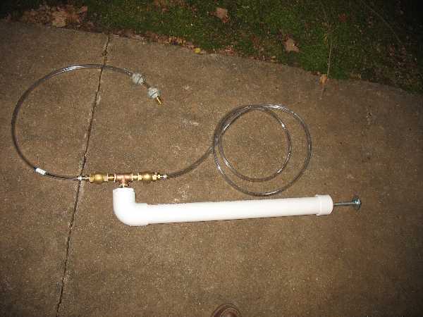
Here is the pump. The body is about 2 1/2 feet long with 3 feet of intake hose and 7 feet of outlet hose.
Bill of materials
The pump body requires the following:
- 2" PVC pipe section. I used 2 feet but anything between 1 and 2 1/2 feet should work ok.
- 2" end cap (slip fit)
- 2" slip fit 90 degree PVC elbow
- 2" slip to 1/2" threaded bushing
- CPVC cement
The pump valve assembly consists of the following items. This should be bronze or brass. I don't like PVC for this part as it may break from rough handling.
- Three 1/2" brass nipples (1 1/2" long)
- One 1/2" brass Tee
- Two 1/2" bronze swing style checkvalves. These resist corrosion and are least prone to obstructions and can be easily cleaned if they do get obstructed. The spring loaded checkvalves aren't really necessary unless you plan to use the pump with it oriented horizontally.
- Two 1/2" barb to thread hose adapters
- Polyurethane adhesive (3M 5200 or equivalent)
The piston is made from the following items. I used zinc plated steel which is adequate. Bronze would hold up longer but is obviously much more expensive.
- 1/2" threaded rod. Mine is 2 feet long. It needs to be as long as the pipe section. I chose 1/2" to avoid the possiblity of buckling and to fit commonly available washer sizes.
- Five 2" x 1/2" fender washers
- Two 1/2" lock nuts
- Two 1/2" lock washers
- Two 1/2" plain nuts
- One 2" O-ring. This has an outer diamter that is about 1/16" diameter larger than the inside of the pipe section. It is about 3/16" thick. It is crucial that this forms a good sliding seal against the inside of the pipe. Some auto parts stores or hardware stores may carry this.
The intake and outlet may consist of the following:
- 10 feet of 1/2" plastic hose
- 1 1/2" hose barb to threaded adapter
Assembly
This takes less than an hour.
First, glue up the 2" to 1/2" bushing to the elbow and the elbow to the 2 foot long pipe section. Drill a 1/2" hole in the top of the end cap. Do not glue the end cap to the pipe section. Set these aside.
Assemble the pump mechanism in the following sequence using the polyurethane adhesive. This forms a good seal and prevents it from casually turning and coming apart.
- Hose barb adapter
- Check valve
- Nipple
- Tee. These go in the opposite ends of the tee.
- Nipple
- Check valve. Make sure both checkvalves are facing the same way.
- Hose barb adapter
Put the remaining nipple in the tee and screw that into the pump body. Glue with polyurethane adhesive. Make sure that the assembly is oriented parallel to the pump body. The checkvalves must allow water to flow up but not down.
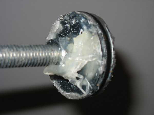
To assemble the piston put a plain nut on the end of the threaded rod. Follow it by a lock washer. Then add two fender washers. With it standing vertically set the O-ring on the top of the fender washers. Then add two more fender washers to the stack. Finally put a lock nut on the very end of the threaded rod.
The next step is to get the O-ring to form an adequate seal against the inside of the pipe. Tighten the nut hand tight against the stack of fender washers and O-ring. Smear some petroleum jelly on the O-ring and on the inside of the pump body. Insert the piston end into the top of the pipe at a 45 degree angle. Then pull the threaded rod parallel to the pipe. Push it in. Try to evenly compress the O-ring as you do this. It will be difficult at first to push it in until the petroleum jelly has coated the inside of the tube. Add a few drops of hand soap and water if necessary. Push it down and pull it up a couple of times to make sure it slips well. You should hear air going in the bottom of the pump assembly and coming out the top. You should also hear the checkvalves clicking. As a last step pull the piston until it almost comes out of the pipe. Tighten the nut until it compresses the lock washer.
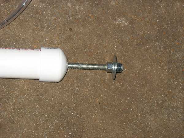
Now fit the end cap over the threaded rod and slip it onto the end of the pipe. It will slip on tightly but can be gently tapped loose if the pump needs to be cleaned or serviced. Put a nut on the end followed by a lock washer, a fender washer and finally a lock nut as shown. This is the handle as the threaded rod is hard to grab. You may want to substitute a piece of wood for the fender washer.
For the intake cut a 3 foot section of the plastic hose and fit it on the bottom hose barb. Then string on something to help hold the hose straight. I had some old galvanized pipe unions on hand to serve as weights. Then fit the remaining hose barb adapter on the end to hold the weights in place. Let the pump sit overnight for the adhesive to cure. Then test by pumping some water.
It works
I tested it by pumping out the bilges. It moved water quite quickly and did not leak. After use I pumped some fresh water through it to flush out any particles from the bilge water. I was able to drain the remaining water out by holding it at an angle with the check valves hanging down. I then tilted it past horizontal so that the checkvalves could swing open and any remaing water could drain out. I think that this should hold up well. The first part to be replaced would probably be the piston and threaded rod but it should last for several years of occasional use.