Repowering
Engine Controls
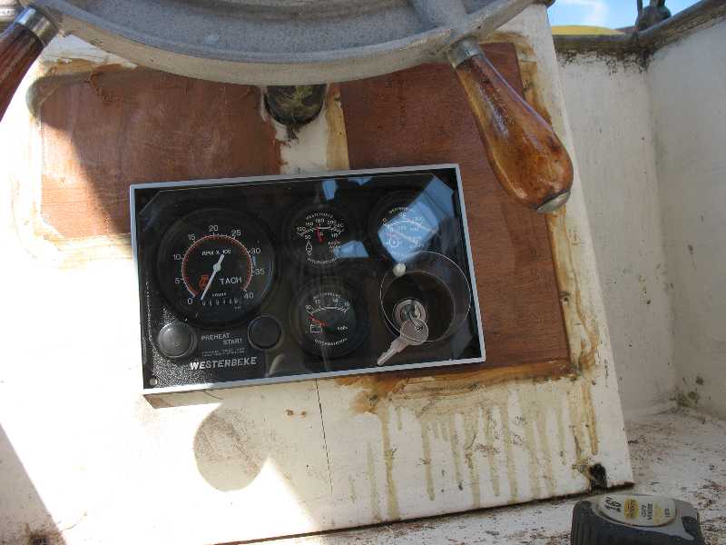
I picked the Admiral control panel option. It offers a lot more information on how the engine is running. The idea is that I might be able to spot developing problems sooner before they get bad.
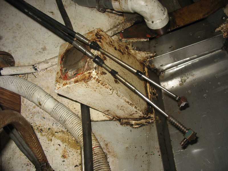
Here are he throttle and shift cable ends. It seems they are just long enough to go to the front of the engine where they are to hook up. I just need to remove the Volvo fitting.
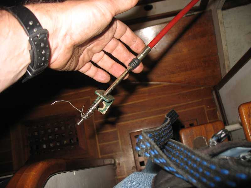
This is the pull stop cable.
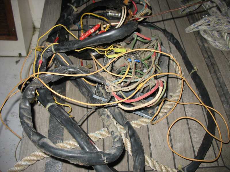
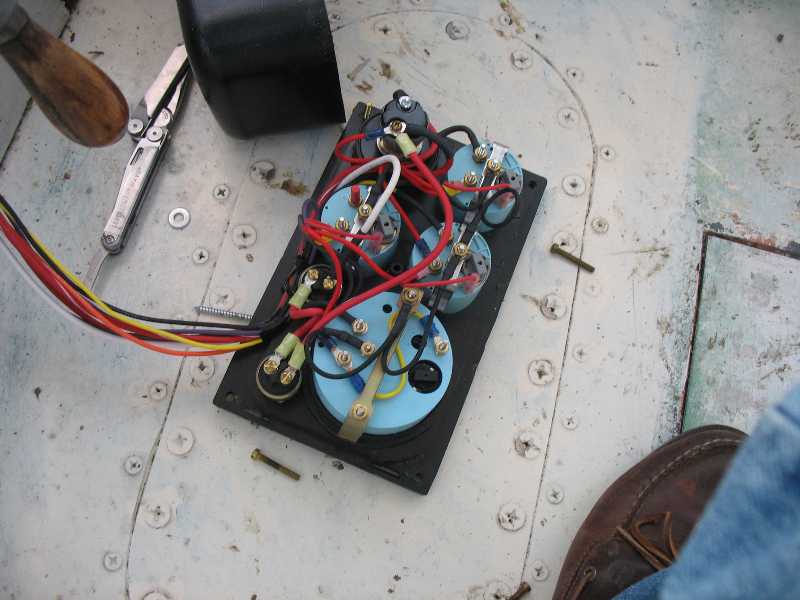
I pulled out the old wiring.
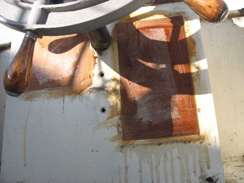
I had to patch the entire console to get a good position for the new control panel.
Here the panel is test fitted. I cut the hole for it with a Fein tool.
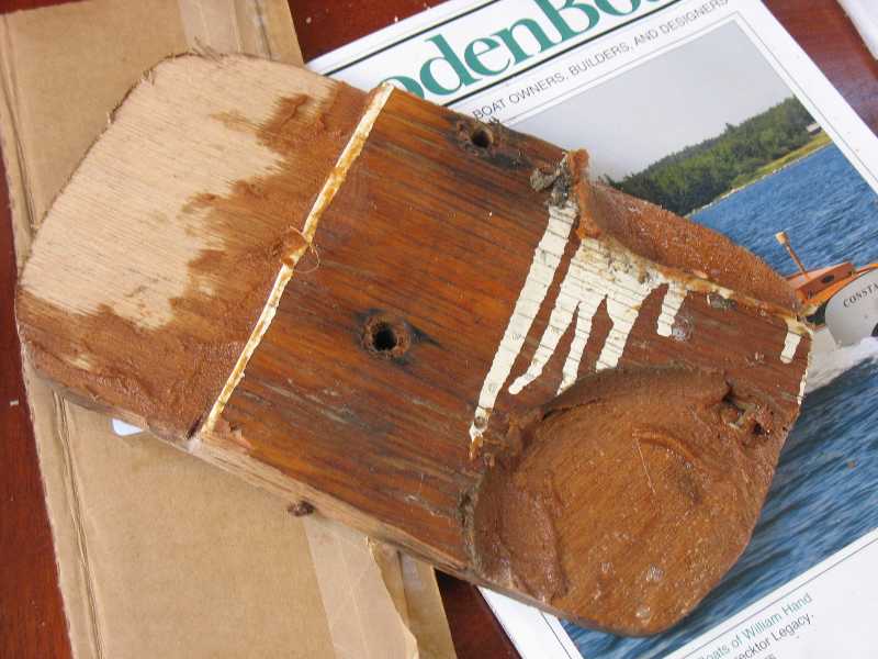
The cutout piece shows a rich history of modifications. Parts of three
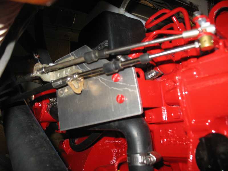
I used an aluminum plate and two teleflex cable mounts from the Volvo to get a firm, reliable connection. It is paramount that this be done right.
One final task remained - to calibrate the tachometer. The Westerbeke reads off the AC output of the alternator. Because of various options in the control panel and alternators this is not done at the factory.
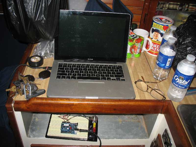
I used a simple LED strobe light driven by an Arduino board with a simple timing sketch that prints out the results to the computer. I illuminated the crankshaft wheel on the engine with the strobe. I then adjusted the frequence with a potentiometer until the wheel appeared stationary. Thus the strobe frequency matched the engine rotation. The Arduino counted the number of strobes per second and multiplied by 60 to get the RPM.
I then adjusted the tachometer to suit.
This proved accurate enough for basic calibration. It was at zero additional cost whereas a commercial unit would have cost several hundred dollars.
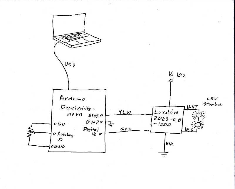 Here is a circuit diagram of the strobe device.
|
int threshPin = 0; int ledPin = 13; int val = 0; int threshold = 0; void setup() { } void loop() { } |
Here is the sketch I used