Repowering
Electrical Hookup
The new engine uses an electrical hookup similar to what the old engine had. I will continue to use the alternator for charging both the starting and house batteries. I will still have the ammeter and voltmeter setup for monitoring alternator output.

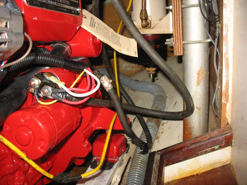
Shown here are the ground wire, the charging wire and the starter power wire. One of my tasks is to verify where on the engine these need to hook up.

Dave and I attached these on the right hand side. The starting positive attached to the starter. The starting ground attached to a ground indicated on the engine. The house ground is the yellow wire also attached to the engine.

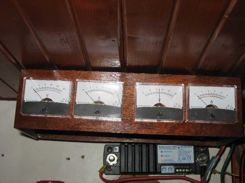
The new engine by default charges the starting battery back through the starting cable. Rather than modify the engine's electrical system I decided it was best to reverse the battery combiner. I rewired things so that when the engine starts up it is charging only the starting battery. When the battery combiner senses a charging voltage around 14 volts it starts a timer. After about one minute it switches in the house battery so it also gets charged. After the engine is shut down and a minute passes it breaks the connection.
The wires are a bit more tidy than before too. Eventually I will put a grate cover over this that can be opened to turn the switches.

The solar panel system charges the house battery all the time.

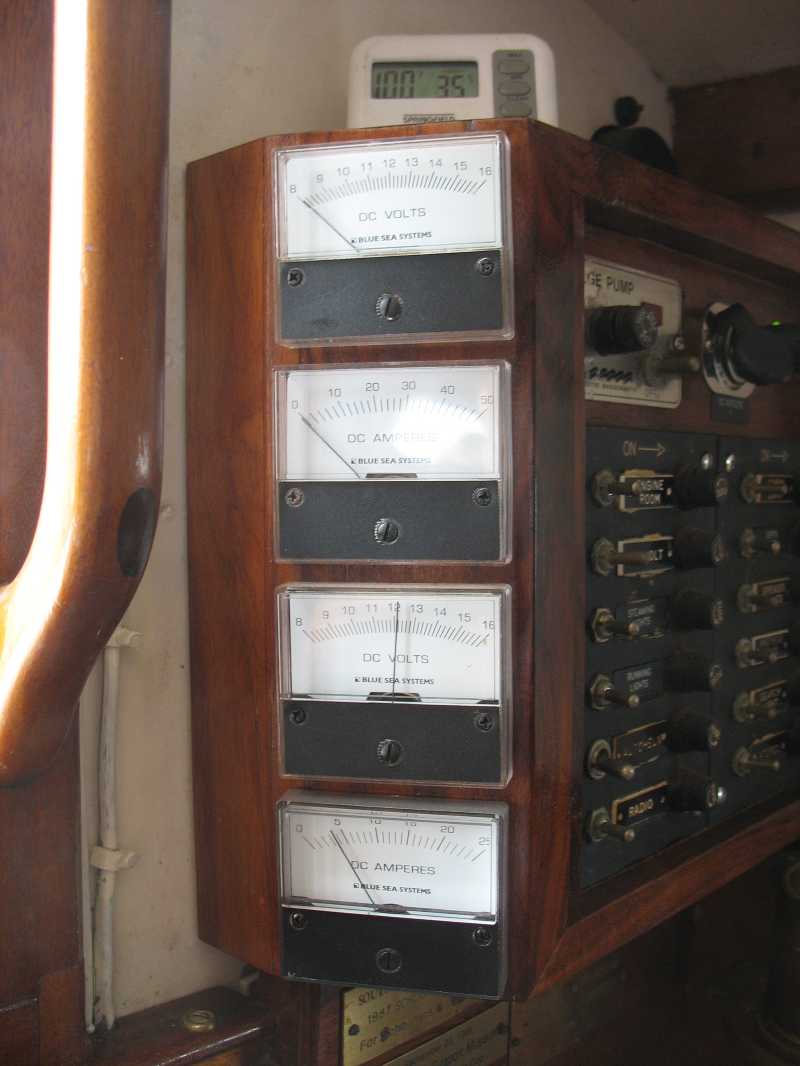
On the house console the top volt meter indicates starting battery voltage and alternator output voltage. The top ammeter indicates the current coming into the house wiring from the alternator.
As you can see atop the console it was quite a roasting hot day as I worked.